Simon Fell > Its just code > June 2021
Wednesday, June 9, 2021
I've been working on an SFX100 build. Yeah i know its been a long time, you thought it was long finished. Not so much.
Back in October I'd started on the 3D printing. I got a single set of prints completed, and went through the process to assemble the first actuator. This went reasonably well. The instructions are pretty good, I used a dab of superglue to hold the o-ring onto the bump stop and discovered that you can't get the grease gun on once the slider is fitted to the ball screw. Easy enough to unscrew the slider and then grease the ball-screw. With this success I was in full on 3D printing mode for a couple of weeks to print parts for the remaining 3 actuators. A couple of weeks later, and I'm assembly the 3 remaining actuators. That's when I started running into problems.
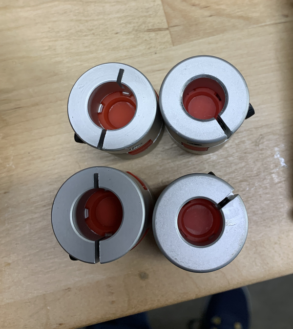
First off, I noticed that the couplers were different sizes, I'd gotten 2 the right size, and 2 that were smaller.
 .
.
The folks over at ntl-bearing.com quickly sent me 2 replacements.
Then i hit bigger problems. Remember back when I said it was important to get the profile inserts in square, this is why.
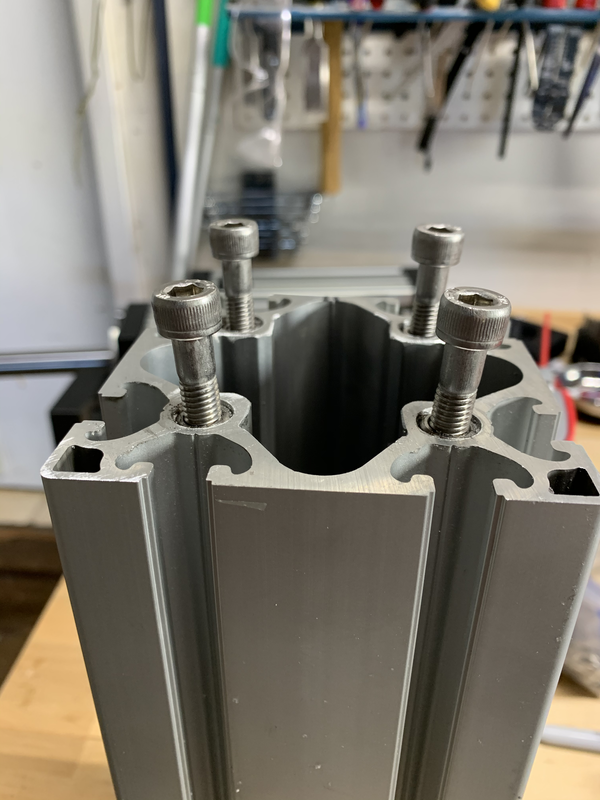
You can see here that the left side bolts aren't square to the profile, especially
the front left. The top bearing mount design has standard clearance holes for the bolt, but is deep enough that with the
angled bolt you can't get all the bolts through the bearing mount and into the profile. One profile I couldn't get the
bearing mount on at all. The second one I managed to get on, but it got pulled off center and the actuator travel was
really stiff and noisy. You can't get the inserts out of the profile, so its either buy new profile and redo these 2, or
redesign the bearing mount to allow the bolts a bit more room. This only reenforces my earlier recommendation to build the
Item24 variation and have Item24 tap the profile for you.
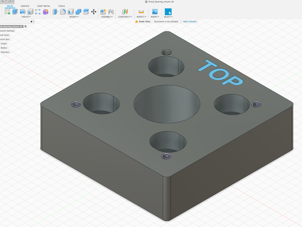
I set about tweaking the bearing mount design. Fusion360 wouldn't import the STL file due to the large number of triangles
in it as a result of their being threaded holes in the model. And only STL files are published for the 3d printed parts.
So i set about recreating it from scratch in Fusion 360. This wasn't too bad, its a rectangle with some holes in it. Most
of the time was spent on checking the dimensions of the hole for the bearing to sit in. I then updated the model to add
a small slot to the bolt holes.
I printed a draft and test fit it and everything seemed okay. Went back and did final prints of 2 more. A few days
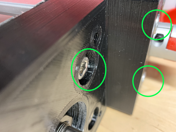
later back to assembly. Now, when i did the test fit, i was concentrating on the bearing placement, getting the bolts in
and tightened up and checking that the screw-ball was still square and travelled okay. What I didn't check was the motor
mount that fits on top of the bearing mount. You can see here that I screwed up the depth of the bolt recess and the top
of the bolts protrude slightly above the top of the bearing mount. (left good, right bad)
 .
.
Bah. back to Fusion 360, tweak the design, print some more.
We're now well into December, and it is much colder (relatively, it is California after all) in the garage where the 3D printer lives than it was before. I tried printing the 2 bearing mounts again, and had all sorts of issues. First layer wouldn't stick, and very poor adhesion between layers. After a number of attempts and some research I found some discussions of how the ambient temperature can affect prints. I experimented with different hot-end temperatures and was able to get some better prints, I ended up printing at 220 vs the original temperature of 200. At this point I was tired of fighting the printer on 15 hour prints, and turned to a couple of other projects for a while.
After having enough successful smaller prints, I finally got around to trying to print the bearing mounts again. I kicked off the
print, it seemed to be going well. Checked in after 13 hours, still going strong. Come back when it should of finished to find
this. 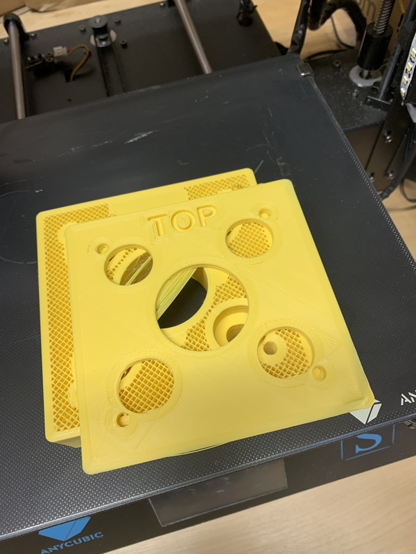
I was (and still am) baffled by this, it looks like it just shifted the X and Y
by 100mm at a particular layer. This doesn't seem to be the regular layer shift problems, which are typically mechanical and accumulate
small amounts of drift over many layers. The fact that both X and Y are offset the same amount also implies its not a mechanical issue.
Possibly a bug in the slicer? Possibly something caused Octoprint to miss some steps from the g-code? I still don't know. Without
knowing why it failed I was loathed to try it again. I put it down again, and went and worked on some other projects.
More time passes, I don't see the issue again. I have a 12 hour print go fine. I finally get around to trying the bearing mount again.
That one comes out fine, some slight curling at the corners, but that's to be expected and not a problem. I assemble and test actuator #3,
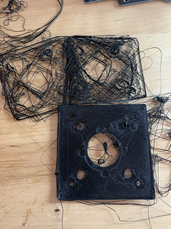
success!. I kick off the final print, and a few hours later am greeted by this.
 .
.
As far
as i can tell, the corners curled enough to unstick the print from the bed, and chaos ensued. More research, I find some recommendations
to start with the part cooling fan off and have it ramp up over the initial layers. I fiddle with slicer settings some more, and kick
off another print. Its running as a type this. It looks okay so far, there's some curling but its less than it used to be. Hopefully
this one completes successfully.
Update: It didn't